
where : ibrtses embedded
AVR RC Oscillator calibration to an XTAL
A recent project required me to work with an RC driven Mega169P. The setup
just had the RC plus a 32kHz Quarz. The calibrateable RC oscillator has a
tuning graph as
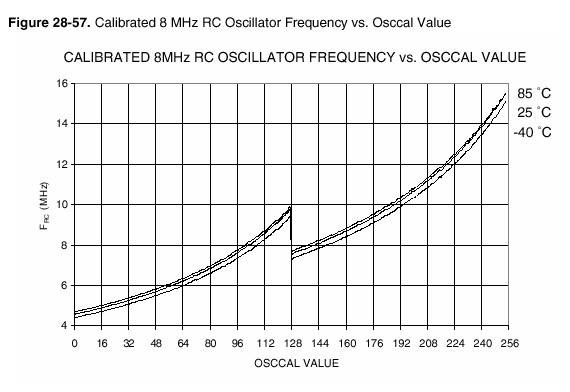
Taken fom the Mega169P manual 8018I-AVR-11/06, page 363
and I wanted to have the clock at the either timing convenient 8MHz or at
the baudrate convenient 7.3728MHz. First came the manual approach
manual frequency tuning
The manual tuning is not that hard. Have a 16bit timer running to produce say 10ms if it
was running at the desired frequency. Then either poll the timer overflow flag (or have
an interrupt) and toggle a pin. On the scope measure the pin and edit the value until the
period matches.
Since the scope doesn't have the correct resolution, the following code uses two timers
against each other. One as reference, the other for the Osc. It initializes the two timers,
timer2 for the 32kHz XTAL and timer0 for the supposed 10ms tick. The 32kHz clock produces
pulses at 1Hz, which are compared to the 10ms tick. Any other combination is also thinkable.
// timer0 is the 10ms tick from the 7.3728MHz or 8MHz Clock
// This is the 10ms system tick
SetupTimer0:
	ldi	temp,0x05	; clk div 1024 = 128us @8MHz
	sts	TCCR0,temp      ;             or 138.8us @7.3728MHz
	ldi	temp,184	; 256-78 for 10ms @8MHz
	sts	TCNT0,temp      ; or 256-72 for 10ms@7.3728MHz
	ret

// Setup timer2 for 1Hz and enable timer0
//
CalibrateManual:
	ldi	temp,0x44	; for 7.3728MHz ** enter this
	sts	OSCCAL,temp     ;           value manually **
	ldi	temp,0		; Timer2 off
	sts	TCCR2A,temp
	ldi	temp,0x07	; div 1024
	sts	TCCR2A,temp
	ldi	temp,223	; 255-32 for 1 Hz
	sts	TCNT2,temp
	ldi	temp,0x08	;
	sts	ASSR,temp
	ldi	temp,0x01	; enable Timer0
	sts	TIMSK,temp
	ret
Why are two procedures above ? The Tick ist used anyway, The CalibrateManual
is replaced by intializing the OSCCAL in the normal Init. Now the interrupts.
They both basically just reload the counters, and toggle a pin. The pins are
from the application unused pins.
interrupt timer0
	push  ...
	ldi	temp,184	; 256-72 for 10ms
	sts	TCNT0,temp
	sbi	PORTB,6		; make a pulse
	cbi	PORTB,6
	pop ...
	iret

interrupt timer2
	push ...
	ldi	temp,223	; 255-32 for 1 Hz
	sts	TCNT2,temp
	sbi	PORTE,6		; make a pulse
	cbi	PORTE,6
	pop ...
	iret
I has been shown by calibarting different units of the same hardware, that the
values for OSCCAL are almost independent on the voltage, a bit dependent on the
temperature, but very dependent on the specific controller itself. While for
one example the value was 0x44, with another, it was 0x5C. This means there is
no simple factory preset solution. This led to the automatic tuning described
now. Yes, a thinkable intelligent programmer could do a calibration itself.
Such a solution would then be dependent on the supply- and temperature condition
during the programming.
automatic frequency tuning
This version of the automatic tuning is done at powerup once. It starts with the
OSCCAL at the lowest and increases until the period is short enough. Here, to have
a sufficiently quick calibration the XTAL runs in an overflow mode, meaning it counts
from 0 to 255 and sets the overflow flag every 7.8125ms. While the timer2 counts
round, the software loop counts number of loops it can do incrementing a 16 bit
counter. At approximate 9000 counts per period, the resolution is sufficiently fine.
Before it is forgotten, the interrupts are disabled here.
If the temperature and supply conditions change considerably such that the UART
is not operating reliably anymore, another dynamic, meaning periodic calibration
will have to be considered.
CalibrateRC:
	ldi	temp,0
	sts	OSCCAL,temp
; init Timer2 as Async Timer
	ldi	temp,0		;Timer2 off
	sts	TCCR2A,temp
	ldi	temp,0x08	;Timer2 Async
	sts	ASSR,temp
;	ldi	temp,0x02	;timer2 div 8, on
;	sts	TCCR2A,temp	; overflow every 62.5ms
	ldi	temp,0x01	;timer2 div 1, on
	sts	TCCR2A,temp	; overflow every 7.8125ms
OptLoop1:
	ldi	ZL,0
	ldi	ZH,0
waitcrc1:
	in	temp,TIFR2
	andi	temp,0x01
	breq	waitcrc1
;	sbi	PORTB,6		;debug ******
;	cbi	PORTB,6		;debug ******
	ldi	temp,0x01
	out	TIFR2,temp
waitcrc2:			; counting loop takes 6 cycles
	adiw	ZH:ZL,1		; thus countin target is 9600
; wait for here
	in	temp,TIFR2
	andi	temp,0x01
	breq	waitcrc2
;	sbi	PORTB,6		;debug ******
;	cbi	PORTB,6		;debug ******
	ldi	temp,0x01
	out	TIFR2,temp
;	ldi	temp,0x62	;send 0x62 through the UART
;	sts	UDR,temp
; compare the Z with 9600
	cpi16	ZL,ZH,9600
	brcc	OptEnd
; still too low

	lds	temp,OSCCAL
	inc	temp
	sts	OSCCAL,temp
	rjmp	OptLoop1
OptEnd:
	ret

The optionally inserted 0x62 for the UART serves as visual
check for the scope.
There are a few more thinkable solutions, all of which are rather simple and take
just a few ASM lines. They provide a working, calibrated RC oscillator with little
effort.
Yes, before it is forgotten. Atmel has an Appnote, AVR053, where the STK500 or so
does that. There is another Appnote AVR055, where they also use a 32kHz Quartz for
the RC calibration. They have the focus rather on quickness and operate with binary
seaches for a quick calibration and use in the order of 300 bytes for that, about 5
times more than the above solution.
The above outlined calibration freely uses timer resources, and this is less of a
problem in a bootloader. To the contrary, this is hardly doable in an application.
A dynamic calibration has to be made to fit into the application. A serially serving
device (always able to receive) can never have the baudarte too far off. Changing
the interrupt behaviour require carefull considerations. We either haven't gone this
far, or didn't consider publishing it yet.
Comments are welcome.
Questions ?
Suggestions?
Feedback ?

sponsored links
home
the embedded pages
the AVR pages
last updated 21.oct.07, or perhaps later
Copyright (99,2007) Ing.Büro R.Tschaggelar