
microwave resonator optimizations
A W-band (90GHz) resonator used for EPR in physical chemistry research
had quite a number of parameters that
were arbitrarily choosen. Tests revealed that it didn't perform
as expected. Microwave studio from CST was used
for the simulation to find the influence of the various parameters.
The structure in question is a round resonator with a quartz tube sample,
fed by a rectangular waveguide. As can be seen from a cut view :
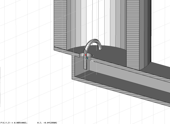
there are some parameters apparent.
- the position and length of the coupling wire into the rectangular waveguide
- the position, diameter and angle of the loop into the round resonator
- diameter and length of the resonator
- cuts and grooves to suppress unwanted modes in the resonator
Of interest is the dependence of the Q from the parameters as well as
the modes in the resonator, the shift induced by the quartz tube sample.
The coupling between rectangular and round waveguide
As first approach, the coupling was calculated between the extended
round waveguide and the rectangular waveguide. While the round
waveguide was fed with a circulare TE mode, the output on the
rectangular waveguide was measured as TE mode. Then some of the
parameteres were swept. It was found the coupling is dependent on
- the wire into the rectangular should be half the waveguide
height in length
- the wire should be lambda half from the ending wall
- the position of the hole between 0.7 and 1.4mm has the best
broadband performance at 0.7mm
- the angle of the wire between 0 and 40 degrees gives strange
alternating results.
- the hole diameter between 0.4 and 0.8mm does not matter much
- the loop diameter between 0.8 and 1.6mm does not matter much
- the wire diameter between 0.1 and 0.6mm does not matter much
The coupling was in the order of -20 to -10dB broadband from 86GHz up,
where the round part started to conduct.
A sample parameter sweep shows the coupling in dependence of the loop
diameter : 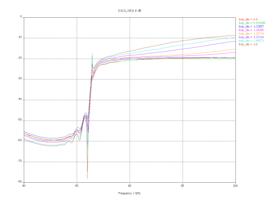
The modes in the resonator
While the coupling between the waveguides is disturbingly independent of most
of the parameters, the propagating modes are not. Especially when the round
waveguide becomes a resonator. So as next step, the round waveguide was changed
to a resonator. It was immediately visible that there were multiple modes competing
with the circular TE mode. The circular TE mode is unique by not having current
through the top and bottom plates. Therefore circular groves at the top and
the bottom plate as well as the hole for the quartz sample tube prefer the circular
TE mode. A sample video (420k). Another
one (9.7M)
The field homogenity was found to be acceptable. The E-field at resonance looks
like
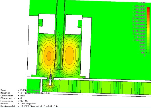
While the H-field looks like
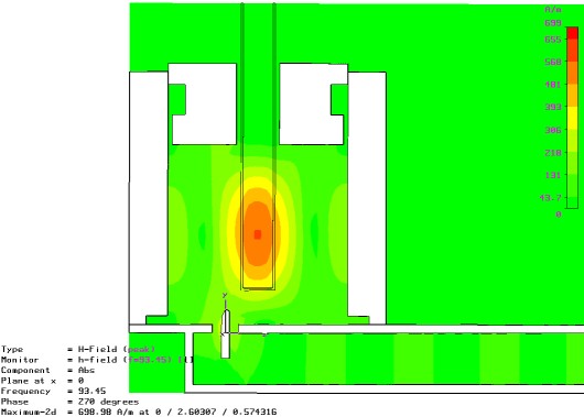
Yes, building this resonator was a different story. The parts were rather tiny.
simulations page
ibrt home page
last updated 8.dec.04
Copyright ibrt (1999-2004)